Uncategorized files
Jump to navigation
Jump to search
Showing below up to 50 results in range #7,451 to #7,500.
-
 751.22 Open Int Bent Diaphragms Dim Part Elevations.gif 744 × 500; 25 KB
-
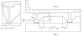 751.22 Open Int Bent Diaphragms Dim Part Elevations.jpg 1,084 × 485; 80 KB
-
 751.22 Open Int Bent Diaphragms Dim Part Plan.gif 744 × 500; 25 KB
-
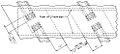 751.22 Open Int Bent Diaphragms Dim Part Plan.jpg 493 × 221; 53 KB
-
 751.22 Open Int Bent Diaphragms Dim Part Section.gif 744 × 500; 25 KB
-
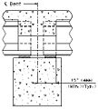 751.22 Open Int Bent Diaphragms Dim Part Section.jpg 232 × 257; 37 KB
-
 751.22 Open Int Bent Diaphragms Reinf Part Elevations.gif 744 × 500; 25 KB
-
 751.22 Open Int Bent Diaphragms Reinf Part Plan.gif 744 × 500; 25 KB
-
 751.22 Open Int Bent Diaphragms Reinf Part Section.gif 744 × 500; 25 KB
-
 751.22 Section Thru Girder 2-6.gif 168 × 278; 5 KB
-
 751.22 Section Thru Girder Type 7.gif 236 × 317; 5 KB
-
 751.22 Shear Blocks Elevation View.gif 629 × 151; 6 KB
-
 751.22 Shear Blocks Elevation View Open Diaphragm.gif 526 × 134; 5 KB
-
 751.22 Shear Blocks Plan View.gif 625 × 133; 3 KB
-
 751.22 Shear Blocks Plan View Exp Bts Closed Diaphragms.gif 610 × 231; 5 KB
-
 751.22 Shear Blocks Plan View Exp Bts Open Diaphragms.gif 607 × 179; 4 KB
-
 751.22 Standard PSI Girder End Section.gif 744 × 500; 25 KB
-
 751.22 Superelevation Slope.gif 372 × 214; 4 KB
-
 751.22 Theoretical Slab Haunching Diagram.gif 744 × 500; 25 KB
-
 751.22 Vent Holes Elevation & Section.gif 597 × 252; 7 KB
-
 751.22 anchorage zone and confinement reinforcement.gif 744 × 500; 25 KB
-
 751.22 coping detail.gif 744 × 500; 25 KB
-

-
 751.22 dim NU girders 29 35.gif 744 × 500; 25 KB
-
 751.22 dim NU girders 43 53.gif 744 × 500; 25 KB
-
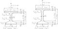 751.22 dim NU girders 43 53 Apr 2011.jpg 998 × 504; 57 KB
-
 751.22 dim NU girders 63 70.gif 744 × 500; 25 KB
-
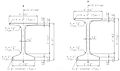 751.22 dim NU girders 63 70 Apr 2011.jpg 874 × 517; 52 KB
-
 751.22 dim NU girders 78 94.gif 744 × 500; 25 KB
-
 751.22 dim beam types 2 thru 6.gif 636 × 284; 14 KB
-
 751.22 dim beam types 7 8.gif 611 × 308; 10 KB
-
 751.22 harped strand layout.gif 613 × 245; 6 KB
-
 751.22 hold-down device.gif 457 × 148; 4 KB
-
 751.22 optional conc PSI span ranges.gif 702 × 801; 33 KB
-
 751.22 span & structure lengths integral end bents.gif 744 × 500; 25 KB
-
 751.22 span & structure lengths integral end bents Mar 2011.gif 744 × 500; 25 KB
-
 751.22 span & structure lengths non integral end bents.gif 744 × 500; 25 KB
-
 751.22 span & structure lengths non integral end bents Mar 2011.gif 744 × 500; 25 KB
-
 751.22 standard conc PSI span ranges.gif 707 × 842; 34 KB
-
 751.22 typ continuous PS structure Integral End Bents.gif 744 × 500; 25 KB
-
 751.22 typ continuous PS structure Non Integral End Bents.gif 633 × 156; 5 KB
-
 751.23 double tee curved structure detail.gif 540 × 521; 10 KB
-
 751.23 double tee diaphragm reinf. for end bent int bent.gif 607 × 225; 8 KB
-
-

-
 751.23 double tee optional constr joint.gif 507 × 471; 7 KB
-
 751.23 double tee optional constr joint sec aa.gif 344 × 131; 4 KB
-
 751.23 double tee vent hole details.gif 489 × 150; 4 KB
-
 751.23 part plan of ps conc dbl tee girder.gif 536 × 346; 7 KB
-
 751.23 section thru double tee.gif 491 × 189; 4 KB


