Uncategorized files
Jump to navigation
Jump to search
Showing below up to 50 results in range #7,001 to #7,050.
-
 751.14 int web stiffener (one side only) variable flange width.gif 744 × 500; 25 KB
-
 751.14 lateral bracing-constant-variable depth girders.gif 558 × 147; 4 KB
-
 751.14 lateral bracing-constant depth girders.gif 550 × 166; 3 KB
-
 751.14 lateral bracing-tapered-variable depth girders.gif 531 × 166; 5 KB
-
 751.14 lateral bracing detail a.gif 744 × 500; 25 KB
-
 751.14 lateral bracing detail a.jpg 601 × 575; 43 KB
-
 751.14 lateral bracing detail a Mar 2011.gif 744 × 500; 25 KB
-
 751.14 lateral bracing detail b.gif 446 × 276; 9 KB
-
 751.14 lateral bracing detail c.gif 318 × 285; 6 KB
-
 751.14 longitudinal web stiffener.jpg 544 × 713; 28 KB
-
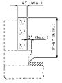
 751.14 longitudinal web stiffener (one side only).gif 744 × 500; 25 KB
-
 751.14 part elevation of girder-constant depth-end span.gif 686 × 284; 12 KB
-
 751.14 part elevation of girder-constant depth-interior span.gif 639 × 239; 7 KB
-
-
 751.14 part elevation of girder-variable depth girder.gif 744 × 390; 16 KB
-
 751.14 part lateral bracing framing plan1.gif 631 × 329; 10 KB
-

-
 751.14 plan of end diaphragm connection for steel structures.gif 290 × 391; 8 KB
-
 751.14 plan of shear connector unit.gif 244 × 136; 3 KB
-
-
-
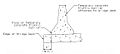
 751.14 section thru haunch showing shear connectors.gif 289 × 145; 4 KB
-

-
 751.14 spacing of intermediate diaphragms from splice.gif 548 × 466; 10 KB
-

-
 751.14 three-span structure.gif 242 × 51; 1 KB
-

-

-

-
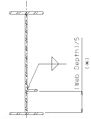
 751.14 welded shop splice.gif 456 × 277; 6 KB
-
 751.14 welded shop splice plan.gif 517 × 189; 3 KB
-
 751.14 welded shop splice section a-a.gif 517 × 187; 4 KB
-
 751.14 welded shop web splice.gif 517 × 255; 5 KB
-
 751.1 Figure 1 Probability Mass Functions.gif 744 × 500; 25 KB
-
 751.1 Figure 2 Cumulative Distribution Function.gif 744 × 500; 25 KB
-
 751.1 Figure 3 (a) PDF and (b) CDF.gif 744 × 500; 25 KB
-
 751.1 M-40a Prelim Design request for final soundings.gif 744 × 500; 25 KB
-
 751.1 M-40a Prelim Design request for final soundings.pdf 1,275 × 1,650; 7 KB
-
 751.1 M-40b Prelim Design soundings layout.gif 744 × 500; 25 KB
-
 751.1 M-40b Prelim Design soundings layout.pdf 1,275 × 1,650; 7 KB
-
 751.1 Prelim Design Acceptable Rail No. 1.gif 744 × 500; 25 KB
-
 751.1 Prelim Design Acceptable Rail No. 2.gif 744 × 500; 25 KB
-
 751.1 Prelim Design Acceptable Rail No. 3.gif 744 × 500; 25 KB
-
 751.1 Prelim Design Acceptable Rail No. 4.gif 744 × 500; 25 KB
-
 751.1 Prelim Design Acceptable Rail No. 4.jpg 397 × 529; 17 KB
-
 751.1 Prelim Design Acceptable Rail No. 5.gif 744 × 500; 25 KB
-
 751.1 Prelim Design Attached Temp Barrier.gif 744 × 500; 25 KB
-
 751.1 Prelim Design Attached Temp Barrier.jpg 575 × 260; 22 KB
-
 751.1 Prelim Design Berm Elevation.gif 467 × 276; 5 KB
-
 751.1 Prelim Design Blockout on Exist Curb No. 1.gif 744 × 500; 25 KB
_variable_flange_width.gif)


.gif)


_PDF_and_(b)_CDF.gif)


-plate_girder_camber_diagram.gif)
-plate_girder_deflection_diagram.gif)
-theoretical_slab_haunch.gif)